Getting 5V SD-Card Modules to work with 5V Arduinos
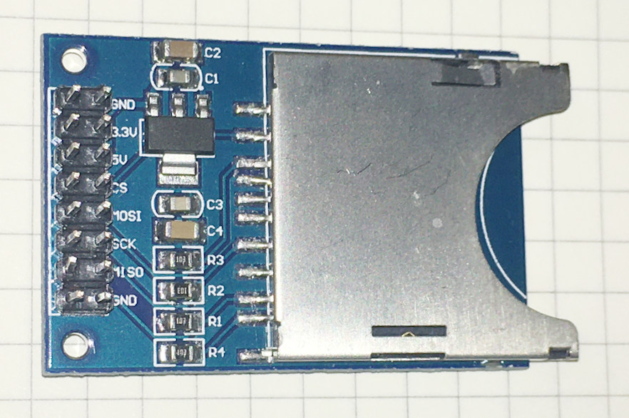
As many have in the past, I bought one of the full-size SD-Card modules shown above. When it came time to use it, it became clear that the module works fine in an all-3.3 V environment, but despite having a 5 V pin on the module, fails to work with 5 V Arduino setups.
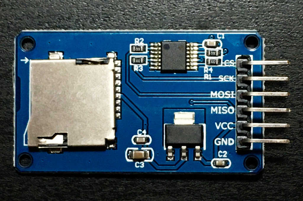
Most modules these days come with a built-in level-shifter IC which converts voltages between 5 and 3.3 volts. Here is an example:
Unfortunately I only had one of the old modules without the level shifter and wanted to get it to work. As SPI lines are all one-way, it should be possible to simply divide the 5 V signals down to 3.3 V. After some experimentation, the following became evident:
1) The MISO line sends data from the SD card to the Arduino. A proper level-shifter would boost the 3.3 V signal up to 5 V. Fortunately, this is not necessary since a 3.3 V "high" signal is high enough to register as a "high" on a 5 V Arduino. So the 3.3 V MISO line from the SD-Card module can be directly connected to the MISO pin on the Arduino.
2) While we would like the resistor divider to add as little load as possible to the signal being output from the Arduino, it also must provide enough current to the input pin on the SD-Card module. Experimentation with an oscilloscope showed that a resistor divider made of 2 k and 4.7 k resistors worked fine for the MOSI and CS lines. And the result a current drain on these IO pins is just about 750 uA, which is a nice low number.
For some reason, the signal from such a divider was too weak to drive the SCK line -- it would be stuck in a high state. A new resistor divider of 470 ohms and 1 k seems to drive the SCK pin reliably. This results in a current drain on high signals on the SCK pin of about 3.4 mA. This is considerably higher than the load on the other SPI pins, but still well within the working range of the Arduino. The complete resistor-divider level-shifting circuit is as follows:

Sharing the SPI Port Between the SD-Card Reader and a Nokia Display
There are some cases where the Nokia display may be slightly corrupted when the hardware SPI port is shared with the SD-Card reader. The easy solution is to place this code after the SD.begin() line, before subsequently writing to the LCD:SPI.setClockDivider(SPI_CLOCK_DIV8); //Slow down the SPIHere is a snippit of code that includes the new line:
//  ==========================================
//  SD-Card Reader Setup
//  ==========================================
  if ( SD.begin( SD_CS ) )
    memcpy_P( &strSpace, &sdCardOK_str, sizeof sdCardOK_str );
  else
    memcpy_P( &strSpace, &sdCardFail_str, sizeof sdCardFail_str );

  SPI.setClockDivider(SPI_CLOCK_DIV8); //Slow down the SPI!

  mylcd.LCDgotoXY( 0, 2 );
  mylcd.LCDString( strSpace );
  Serial.println( strSpace );
It's not clear to me why, but putting the command at the top of the code doesn't work -- the LCD text is still corrupted, though other functions seem to work okay.